A LEGO® Hogwarts Express powered by magic (and IoT)
This project was meant to be started and finished in the space of 3-4 weeks prior to Christmas 2018; I was optimistic at best.
This project started out as being a basic Christmas tree train but ended up being so much more.
Being a massive fan of LEGO® it was a no-brainer to opt for one of their sets given their well-known quality and consistent standards when it comes to their train kits/tracks.
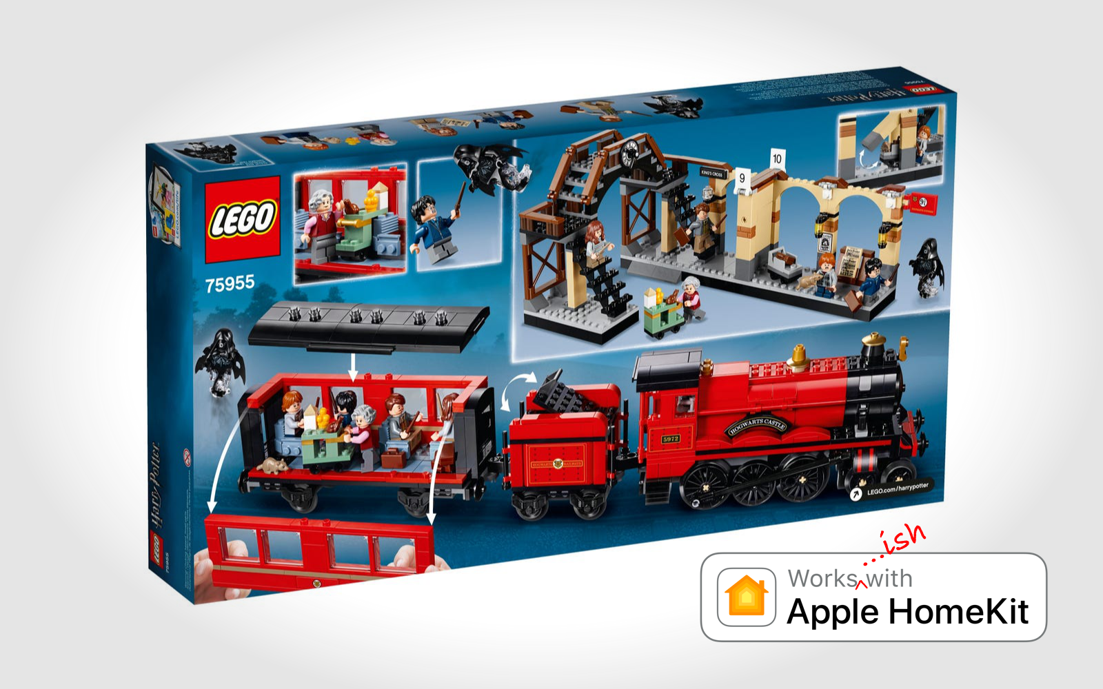
After scoping out the options the Hogwarts Express was the perfect choice given the aim of making the train "smart" would give the illusion of "magic"...
...and it's also just a beautifully detailed model.
The end result being a Homekit controlled "smart" LEGO® train that docks to charge when not in use.
But how did we get here?
The Hogwarts Express kit provided two straight up challenges; firstly, the set isn't motorised by default, and secondly, the kit doesn't come with a track in the box but thankfully it is designed to work on the standard LEGO® train tracks which can be found almost anywhere.
The safest solution for powering the train was internal rechargeable li-ion batteries. I'm not a fan of pulling out batteries to recharge and the persisting wifi connection would result in a slow power draw meaning repeated charging would be unavoidable.
The solution was a compact Uninterrupted Power Supply (UPS) setup leveraging a Qi charging circuit to maintain a power connection when the train is stationary at Platform 9¾.
Phase 1: Motorisation
While there are plenty of other motorized Hogwarts Express projects floating around the Internet, most of them came with a level of aesthetic modification that I didn't like.
After looking at a few of the other projects I figured the best method was to conceal the motor entirely.
To preserve the original look, I would need to custom 3D print a gearbox housing to drive the rear axle, combined with a standard LEGO® Power Functions M-Motor.
LEGO® don't provide detailed spec of their Power Functions motors but given their popularity among hobbyists plenty of details exist on various forums and websites. In particular this one was extremely helpful as it compared almost all of the LEGO® motors that have ever existed.
When it came to modifying the train I had a rule: no mututation to any LEGO® bricks. Any reshaping would have to occur with bricks from other sets or be 3D printed from scratch.
The first few versions relied on a worm gear setup however the ratio resulted in rediculously slow locomotion. I eventually settled on a direct drive setup.
The one time I broke the no mutilation rule was when it came to exposing the M-Motor's wiring, but to avoid modifying the motor itself I instead clipped the connector from an unused control switch and attached that to the motor's propiety connector and eventually crimped some standard dupont connectors onto the four exposed wires.
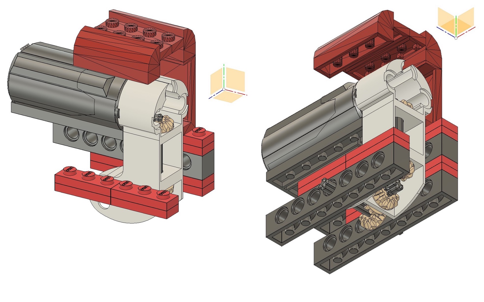
The next step was to size everything up in Fusion 360 where it was a matter of playing with gears to see how I could drive the rear axle using conventional LEGO® gearing.
Then I had to figure out the best way to conceal the motor without too much external disruption. Utilizing enthusiast LEGO® CAD libraries I was able to find some parts that could replace some of the internal structure and shell while also matching colours.
The best "donor" kit I found was the LEGO® "Burger Bar Fire Rescue". Specifically replacing four pieces of the furnace assembly walls with just two that resulted in a larger interal cavity but looked exactly the same on the outside.
This slight modification allowed the motor to sit further forward from the cab and into the furnace/boiler cavity.

The 3D printed housing went through many iterations.
Eventually an all-LEGO® assembly was used.
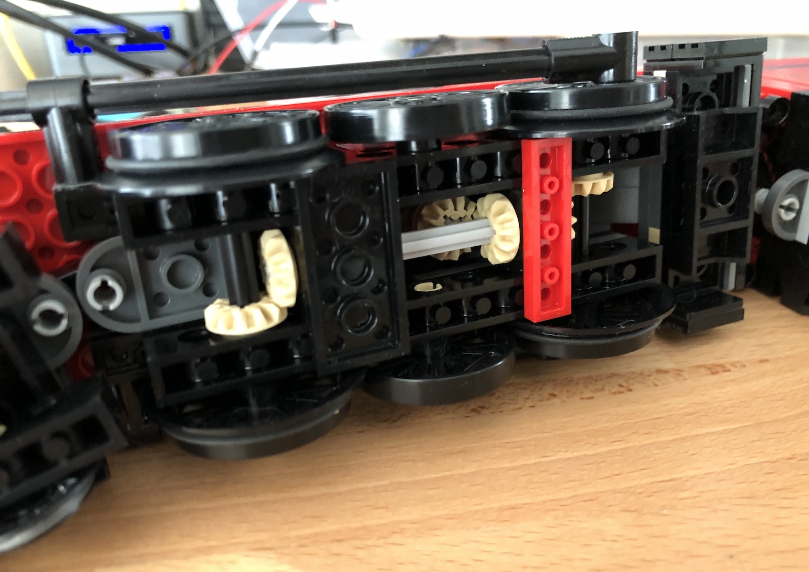
A few months after settling on this 3D printed configuration I'd discovered LEGO®'s Pick A Brick service was open to Australia and ended up redesigning the drivetrain to be 100% LEGO® bricks and was able to move the motor further inside the boiler cavity.
This configuration also allowed for both axles to be driven.
Phase 2: Independant operation
The power requirements were simple; a 9V supply for the motor, 5V supply for the microcontroller, a simple method to charge without human intervention, and enough battery life to run a few minutes without running flat.
The passenger car provides the much-needed space to house all the brains and power.
Thankfully by design the passenger car disassembles with relative ease.
Two lithium-ion 18650 batteries with external protection circuits provide the off-grid power and are charged using the Qi coil housed in the custom underbelly.
The UPS board takes the 5V input from the Qi charging circuit to trickle charge the 3.7V li-ion batteries and provides a boosted output voltage of 9V.
While the 9V output is ideal for the motor, a lower 5V supply provided by the buck converter is required for the microcontroller.
To allow for simple connection of the engine motor I routed the 9V supply, the motor conrol's A1 and A2 pins, and a ground connection to four angled inline pins on the protoboard.
With the motor cable terminated with dupont connectors and the easily accessible angled pins, the passenger car and engine could be connected and separated without any deconstruction.
Not shown in the 3D model was the jumper used to isolate the microcontroller from the onboard power and the 18650 cradles used to avoid soldering connector wires directly to the naked batteries. Safety and modularity were key considerations in this project.
The train was now Working under bespoke battery power with basic motor control programming on the microcontroller and final four wheel drive configuration.
The largest hurdle with the power supply was getting the Qi reciever coil as close to the Qi power transmitter as possible.
The first step was creating an underbelly that gets as close to the top of the tracks as possible without scraping and that is slimmer than the width of the passenger car but cavernous enough to house the entire Qi coil. And then to create a compatible track piece that can replace a standard straight piece and house the Qi transmitter.
Thankfully step one was largely solved from leftover parts from other kits (some inverted slopes and 4x1/6x1 bricks), albeit the colours did not match.
To get the final complete black look I ordered the same blocks, all in black, from LEGO's Pick a Brick service.
In order to get the bottom piece as slim as possible I 3D printed a 6x6 baseplate with only edge studs and the middle section (where the Qi coil sits) being only 4 layers thick.
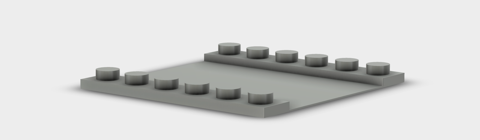
Underbelly plate that contains the train's Qi coil.
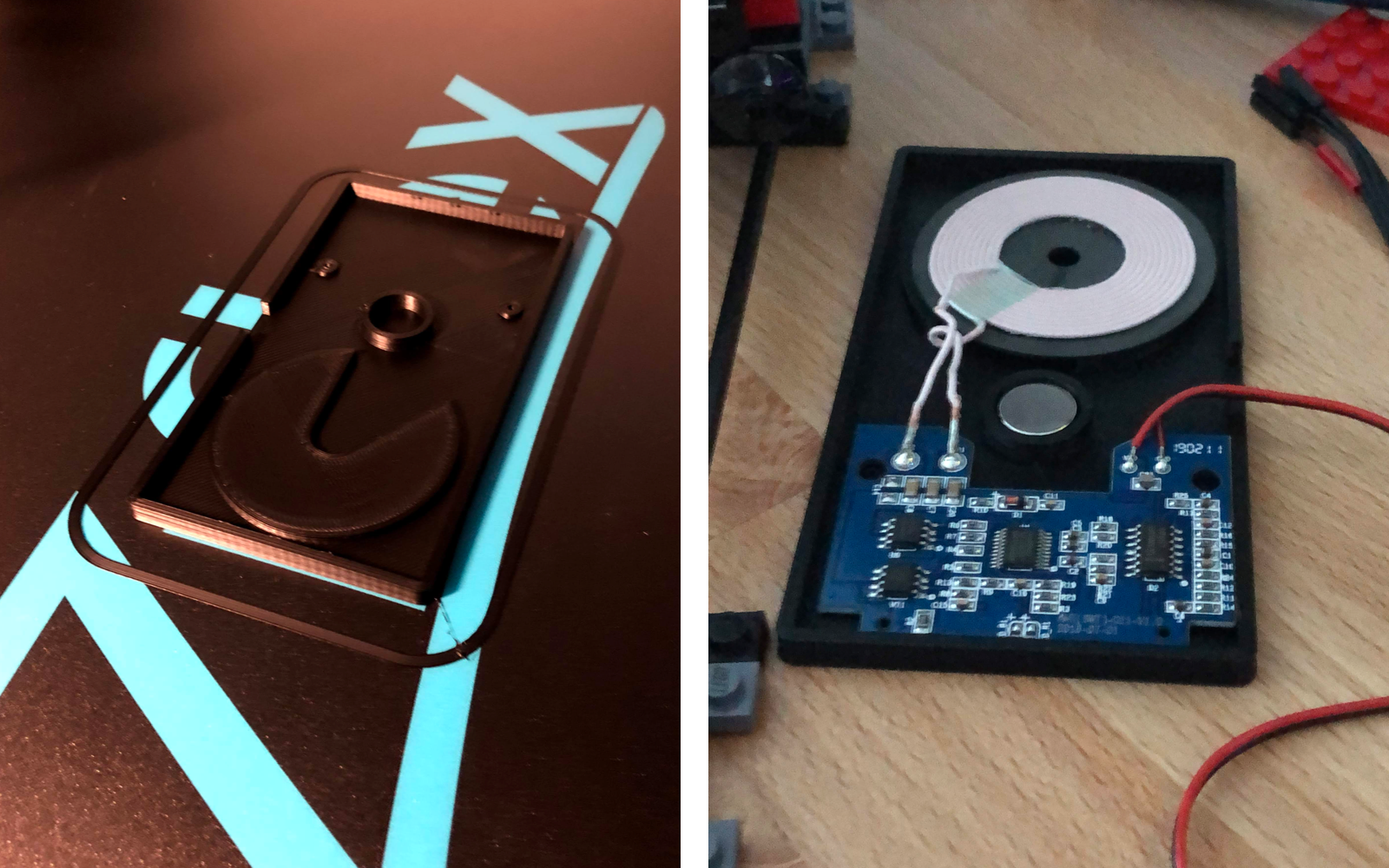
Rare earth magnet is pressed into place and held by friction.
The second step required some planning. Initially my hope for docking was to detect the power delivery and stop the train to remain perfectly above the Qi transmitter, however the Qi "handshake" took longer than expected and as a result I needed another way to detect the charging track section.
I played with a few ideas using some salvaged switches from a DVD drive but the reliability was slim so I eventually settled on a hall sensor mounted ahead of the Qi coil and an embedded rare earth magnet in the track.
The final charging section was printed in two parts; the main base station and the overhanging track section.
This setup was perfectly fine for the first few days of use but as I suspected, and later confirmed, the combination of the weight of the passenger car sitting on the track and the heat generated from the Qi transmitter while charging weakened the PLA and over time the overhanging rail sagged.
The heat wasn't alarming, just high enough to be a problem and so replacement pieces were printed in ABS.
Phase 3: Wifi ability
The microcontroller I chose for this project was the Wemos (now Lolin) D1 Mini, a small, simple, arduino-compatible board based on the ESP-8266EX. It had inherent wifi capabilities, the key to this project.
At this stage in the project I had already assembled the basic Wemos stack that comprised the "magic" of the train for the sake of testing.
The Wemos D1 Mini is sandwiched between a motor shield and a D1 mini shaped protoboard shield.
At this point I learned that the default firmware on the motor control shield was broken from the factory as I had a V1.0.0. I had to flash the shield with fixed firmware (the method requires a USB to serial adapter but a D1 Mini can work in its place as an intermediary).
Rather than posting code blocks here I have compiled everything into a single GitHub repo, including relevant STLs for 3D printing (keep in mind a lot of the code is still a work in progress).
The tldr; of it is the Wemos D1 Mini initially connects itself to the predefined wifi credentials and instantiates a simple web server to listen for requests. Much like any web server it's just a matter of setting up your routes and defining responses.
I've set up some basic routes that return JSON objects containing the train's state, as well as handling some requests that will update some exposed configuration options.
Phase 4: Basic Homekit control
Homebridge is something I've been using extensively for many years.
It allows anyone to create interfaces for devices that are "smart" but otherwise not already Homekit compatible; older LIFX bulbs and Xiaomi smart plugs, for example, are something I use every day and are made infinitely more useful with Homekit/Siri integration. I'd never looked at making a complete custom accesory driver for Homebridge until now.
Again I'll keep the relevant code in the GitHub repo. One thing I learned about Homekit is that even with the Homebridge acting as an intermediary the devices attached to it have to conform to a set list of device types.
For my simple integration I've treated the train as a "smart switch" given it only really has two states; on and off (or "on" and "going home").
Some extra routes needed to be added to the Wemos' code to allow for some basic state checking from Homekit, essentially an "is on" request.
As for referencing the custom train driver I just packaged and installed the module locally with the npm CLI. For the train driver's configuration in homebridge it only requires the module name, accessory id, and device url - I haven't setup any form of discovery so for now I've set my router to reserve the train's IP address for consistency.
With the train module installed, configured in homebridge, and with homebridge running, any device that has access to the "Home" that the Homebridge hub is associated with will have control over the train.
At this point the home app or Siri can control the train. An "on" command will start the train at the default speed of 70% and a "off" command will tell the train to "return home" to find the charging dock so that it's ready for the next trip.
I haven't put the train through a rigorous benchmark but I have managed to (by accident) have it run continuously (at 70% speed) for around 20+ minutes. Standby time is around a few days.
After a year of planning, printing, breaking, and building I finally have my train.
The next steps for this project will involve fixing some potential issues before they happen, mostly adding timeouts to events to ensure nothing is stuck in an infinite loop. If the train is running for ten or more minutes, send it home. If the train is finding home for more than two minutes, maybe it's derailed or stuck and should cut power to the motor.
Once those issues are addressed I'd like to expand the homekit integration, perhaps start out making it work like a dimmer switch, allowing for multiple speeds. Beyond simple on/off control I'd like to experiment with remote track switching and potentially multiple trains.
Appendix: Parts List
Below are a list of project-specific parts, should anyone else want to attempt something similar it's assumed that they have hookup wire, resistors, a soldering iron, a existing homebridge setup etc.
LEGO® Power Functions Motor Set for M-Motor and Swtich. (for brick terminal)
LEGO® Burger Bar Fire Rescue for supplimentary parts. (Pick A Brick alone my suffice)
LEGO® Pick A Brick service for supplimentary parts.
LEGO® City tracks - Will need multiple for a single complete circuit.
Wemos/Lolin D1 Mini - other suppliers exist if the official store doesn't stock the exact board.
Motor Control Shield - as above.
Motor Proto Shield - as above.
9v DC-DC Boost UPS module - I opted for without pins.
2x Battery Protection board - last option on the product.
25mm x 1.5mm O-Rings - for wheel traction.
Micro LEDs - warm white for headlights.
49e Linear Hall Sensor - can be sourced from anywhere.